| |

Physical Layer in OSI ModelThe OSI model is the abbreviation for Open Systems Interconnection Model. It defines the transmission of data from one system to another in a computer network. For example, in the most elemental form, two systems are joined to each other using Local Area Network (LAN) cables and share data with the help of a Network Interface Card (NIC) that allows communication over a network, but if one system is based on Microsoft Windows, and the other is based on macOS, so how would these computers communicate with each other. To successfully communicate between systems of distinct architectures, the International Organization for Standardization (ISO) presented the 7-layered OSI model in 1984. The individual layer of the OSI model is a package of protocols. This article will comprehend the physical layer of the OSI model. 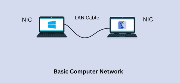
The physical layer is the first and lowest layer from the bottom of the 7-layered OSI model and delivers security to hardware. This layer is in charge of data transmission over the physical medium. It is the most complex layer in the OSI model. 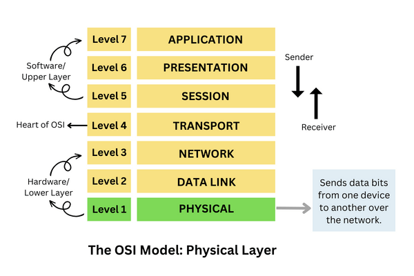
The physical layer converts the data frame received from the data link layer into bits, i.e., in terms of ones and zeros. It maintains the data quality by implementing the required protocols on different network modes and maintaining the bit rate through data transfer using a wired or wireless medium. Attributes of the physical layer:The physical layer has several attributes that are implemented in the OSI model: 1. Signals: The data is first converted to a signal for efficient data transmission. There are two kinds of signals:
2. Transmission media: Data is carried from source to destination with the help of transmission media. There are two sorts of transmission media:
3. Data Flow: It describes the rate of data flow and the transmission time frame. The factors affecting the data flow are as follows:
4. Transmission mode: It describes the direction of the data flow. Data can be transmitted in three sorts of transmission modes as follows:
5. Noise in transmission: Transmitted data can get corrupted or damaged during data transmission due to many reasons. Some of the reasons are mentioned below:
The physical layer performs various functions and services:
Physical Topology:Physical topology refers to the specification or structure of the connections of the network between the devices where the transmission will happen. There are four types of topologies, which are as follows: Star Topology:Star topology is a sort of network topology in which each node or device in the network is individually joined to a central node, which can be a switch or a hub. This topology looks like a star, due to which this topology is called star topology. 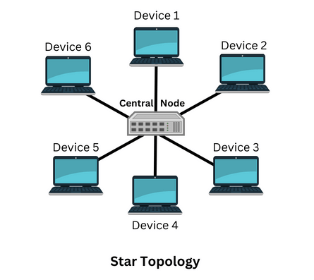
Hub does not provide route data, but it transmits data to other devices connected to it. The advantage of this topology is that if one cable fails, the device connected to that cable is affected, and not the others. Bus Topology:Bus topology comprises a single communication line or cable that is connected to each node. The backbone of this network is the central cable, and each node can communicate with other devices through the central cable. 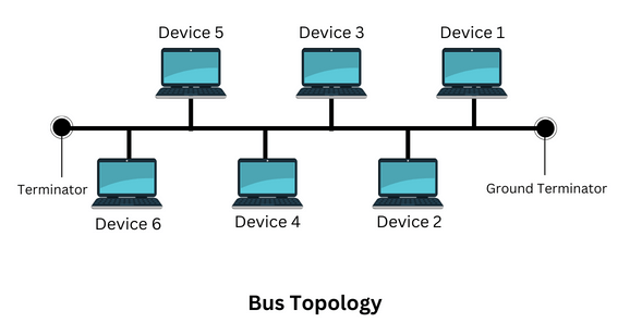
The signal goes from the ground terminator to the other terminator of the wire. The terminator stops the signal once it reaches the end of the wire to avoid signal bounce. Each computer communicates independently with other computers in what is called a peer-to-peer network. Each computer has a unique address, so if a message is to be sent to a specific computer, the device can communicate directly with that computer. The advantage of bus topology is that collapse in one device will not affect other devices. The bus topology is not expensive to build because it uses a single wire and works well for small networks. Ring Topology:In a ring topology, the devices are connected in the form of a ring so that each device has two neighbors for communication. Data moves around the ring in one direction. As you can see below, all four devices are connected to each other in the form of a ring. Each device has two neighbors. Node 2 and Node 4 are neighbors of Node 1; similarly, Node 1 and Node 3 are neighbors of Node 2, and so on. 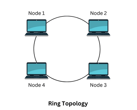
The advantage of ring topology is that if you want to add another device to the ring, you will need an additional cable to do so. Similarly, you can remove a device and join the wires. Mesh Topology:In a mesh topology, each system is directly joined to every other system. The advantage of mesh topology is that there will be no traffic issues as each device has a dedicated communication line. If one system is not functioning, it will not affect other devices. It provides more security or privacy. 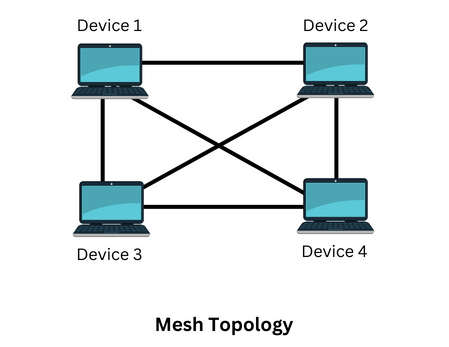
The drawback of mesh topology is that it is expensive and more complex than other topologies. Importance of the physical layer:
Conclusion:
Next TopicData Link Layer in OSI Model
|
 For Videos Join Our Youtube Channel: Join Now
Feedback
- Send your Feedback to [email protected]
Help Others, Please Share


