| |

OSPF ProtocolThe OSPF stands for Open Shortest Path First. It is a widely used and supported routing protocol. It is an intradomain protocol, which means that it is used within an area or a network. It is an interior gateway protocol that has been designed within a single autonomous system. It is based on a link-state routing algorithm in which each router contains the information of every domain, and based on this information, it determines the shortest path. The goal of routing is to learn routes. The OSPF achieves by learning about every router and subnet within the entire network. Every router contains the same information about the network. The way the router learns this information by sending LSA (Link State Advertisements). These LSAs contain information about every router, subnet, and other networking information. Once the LSAs have been flooded, the OSPF stores the information in a link-state database known as LSDB. The main goal is to have the same information about every router in an LSDBs. OSPF Areas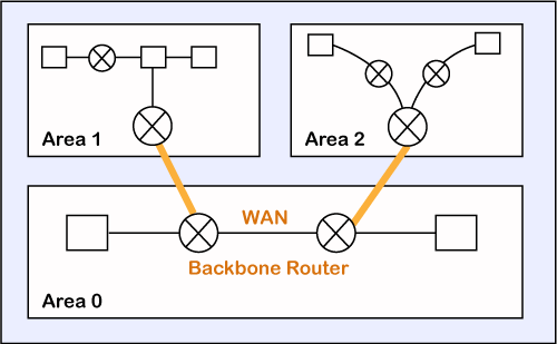
OSPF divides the autonomous systems into areas where the area is a collection of networks, hosts, and routers. Like internet service providers divide the internet into a different autonomous system for easy management and OSPF further divides the autonomous systems into Areas. Routers that exist inside the area flood the area with routing information In Area, the special router also exists. The special routers are those that are present at the border of an area, and these special routers are known as Area Border Routers. This router summarizes the information about an area and shares the information with other areas. All the areas inside an autonomous system are connected to the backbone routers, and these backbone routers are part of a primary area. The role of a primary area is to provide communication between different areas. How does OSPF work?There are three steps that can explain the working of OSPF: Step 1: The first step is to become OSPF neighbors. The two connecting routers running OSPF on the same link creates a neighbor relationship. Step 2: The second step is to exchange database information. After becoming the neighbors, the two routers exchange the LSDB information with each other. Step 3: The third step is to choose the best route. Once the LSDB information has been exchanged with each other, the router chooses the best route to be added to a routing table based on the calculation of SPF. How a router forms a neighbor relationship?The first thing is happened before the relationship is formed is that each router chooses the router ID. Router ID (RID): The router ID is a number that uniquely identifies each router on a network. The router ID is in the format of the IPv4 address. There are few ways to set the router ID, the first way is to set the router ID manually and the other way is to let the router decides itself. The following is the logic that the router chooses to set the router ID:
Two routers connected to each other through point to point or multiple routers are connected can communicate with each other through an OSPF protocol. The two routers are adjacent only when both the routers send the HELLO packet to each other. When both the routers receive the acknowledgment of the HELLO packet, then they come in a two-way state. As OSPF is a link state routing protocol, so it allows to create the neighbor relationship between the routers. The two routers can be neighbors only when they belong to the same subnet, share the same area id, subnet mask, timers, and authentication. The OSPF relationship is a relationship formed between the routers so that they can know each other. The two routers can be neighbors if atleast one of them is designated router or backup designated router in a network, or connected through a point-to-point link. Types of links in OSPFA link is basically a connection, so the connection between two routers is known as a link. There are four types of links in OSPF:
OSPF Message FormatThe following are the fields in an OSPF message format: 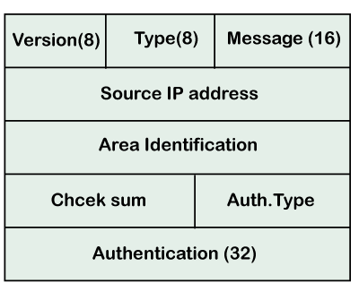
OSPF PacketsThere are five different types of packets in OSPF:
Let's discuss each packet in detail. 1. Hello packet The Hello packet is used to create a neighborhood relationship and check the neighbor's reachability. Therefore, the Hello packet is used when the connection between the routers need to be established. 2. Database Description After establishing a connection, if the neighbor router is communicating with the system first time, it sends the database information about the network topology to the system so that the system can update or modify accordingly. 3. Link state request The link-state request is sent by the router to obtain the information of a specified route. Suppose there are two routers, i.e., router 1 and router 2, and router 1 wants to know the information about the router 2, so router 1 sends the link state request to the router 2. When router 2 receives the link state request, then it sends the link-state information to router 1. 4. Link state update The link-state update is used by the router to advertise the state of its links. If any router wants to broadcast the state of its links, it uses the link-state update. 5. Link state acknowledgment The link-state acknowledgment makes the routing more reliable by forcing each router to send the acknowledgment on each link state update. For example, router A sends the link state update to the router B and router C, then in return, the router B and C sends the link- state acknowledgment to the router A, so that the router A gets to know that both the routers have received the link-state update. OSPF StatesThe device running the OSPF protocol undergoes the following states:
Router attributesBefore going to the Extract state, OSPF chooses one router as a Designated router and another router as a backup designated router. These routers are not the type, but they are the attributes of a router. In the case of broadcast networks, the router selects one router as a designated router and another router as a backup designated router. The election of designated and the backup designated router is done to avoid the flooding in a network and to minimize the number of adjacencies. They serve as a central point for exchanging the routing information among all the routers. Since point-to-point links are directly connected, so DR and BDR are not elected. If DR and BDR are not elected, the router will send the update to all the adjacent neighbors, leading to the flooding in a network. To avoid this problem, DR and BDR are elected. Each non-DR and non-BDR send the update only to the DR and BDR instead of exchanging it with other routers in a network segment. DR then distributes the network topology information to other routers in the same area whereas the BDR serves a substitute for the DR. The BDR also receives the routing information from all the router but it does not distribute the information. It distributes the information only when the DR fails. The multicast address 224.0.0.6 is used by the non-DR and non-BDR to send the routing information to the DR and BDR. The DR and BDR send the routing information to the multicast address 224.0.0.5. Based on the following rules, the DR and BDR are elected:
Let's understand this scenario through an example. 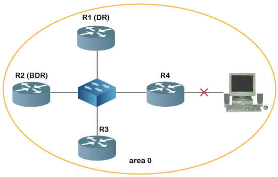
In the above figure, R1 is chosen as the DR, while R2 is chosen as the BDR as R1 has the highest router ID, whereas the R2 has the second-highest router ID. If the link fails between R4 and the system, then R4 updates only R1 and R4 about its link failure. Then, DR updates all the non-DR and non-BDR about the change, and in this case, except R4, only R3 is available as a non-DR and non-BDR.
Next TopicStop and Wait Protocol
|
 For Videos Join Our Youtube Channel: Join Now
Feedback
- Send your Feedback to [email protected]
Help Others, Please Share


