What is Multiplexing in Computer Network
What is Multiplexing?
Multiplexing is a technique used to combine and send multiple data streams over a single medium. Combining the data streams is known as multiplexing, and the hardware used for multiplexing is known as a multiplexer.
Multiplexing is achieved using a device called Multiplexer (MUX), which combines n input lines to generate a single output line. Multiplexing follows many-to-one, i.e., n input lines and one output line.
Although networks use many different multiplexing strategies, they all function conceptually similarly. A multiplexer (mux) receives the different network signals and combines them to create a composite signal.
This composite signal is then sent via a shared medium. Upon reaching its intended location, the composite signal is separated into its component signals by a demultiplexer, also known as a demux, and outputted onto distinct lines for further processing.
Demultiplexing is achieved using a device called Demultiplexer (DEMUX) at the receiving end. DEMUX separates a signal into component signals (one input and n outputs). Therefore, we can say that demultiplexing follows the one-to-many approach.
Why Multiplexing?
- The transmission medium sends the signal from the sender to the receiver. The medium can only have one signal at a time.
- If there are multiple signals to share one medium, then the medium must be divided so that each signal is given some portion of the available bandwidth. For example, If there are 10 signals and the bandwidth of the medium is 100 units, then the 10 unit is shared by each signal.
- When multiple signals share a common medium, collision is possible. The multiplexing concept is used to avoid such collision.
- Transmission services are very expensive.
What is the Purpose of Multiplexing?
- Many different businesses employ multiplexing to enable digital and analogue communications. Initially developed in the 1870s to aid with telegraphy, it has since grown to be a staple in all forms of communication, including phone, television, and radio. Additionally, it is frequently utilized in computer networks to send several signals over a wide area network (WAN).
- Organizations on their networks use multiplexing for two reasons:
- Multiplexing still requires shared media to improve the use of expensive or limited network resources and allow network devices to talk with one another without requiring a dedicated connection between each device pair. Multiplexing, for instance, can send different signals on a satellite uplink or a cable or fibre strand connecting a large metropolis.
History of Multiplexing
- Multiplexing is widely used in telecommunications, where several telephone calls are carried through a single wire.
- Multiplexing originated in telegraphy in the early 1870s and is now widely used in communication.
- George Owen Squier developed the telephone carrier multiplexing in 1910.
Working of Multiplexing
Multiplexing combines numerous signals into one signal for transmission over a single medium, such as a phone line. The input signals can be digital or analogue, depending on the sender. Lowering transmission costs, multiplexing enables messages to be sent more effectively across a particular communication route. The graphic below makes it simple to understand how multiplexing operates.

- A device multiplexer (MUX) is used at the sender end to combine n input lines into a single output line. With n input and one output line, multiplexing uses a many-to-one methodology.
- A Demultiplexer (DEMUX) splits a signal into its signals (one input and n outputs) on the receiving end. Demultiplexing, therefore, uses the one-to-many method.
Advantages of Multiplexing
- Lower Costs: Multiplexing lowers the number of communication channels needed, saving money on equipment, maintenance, and wiring.
- Enhanced Efficiency: This implies that more data may be sent in a shorter time. Multiplexing boosts the communication system's efficiency by enabling the simultaneous transmission of numerous signals over a single channel.
- Flexibility: Multiplexing enables the transmission of various signals over a single channel, including data, video, and audio. As a result, communication systems are more adaptive and responsive to changing requirements.
- Enhanced Quality: By lowering noise and interference, multiplexing can enhance the quality of the delivered signals. This implies a lower chance of signal corruption or loss during transmission.
Disadvantages of Multiplexing
- Possibility of Interference: Multiplexing adds more signal interference possibilities by mixing several signals into a single channel. This may lead to transmission mistakes and a deterioration in signal quality.
- Complicated Design: For individuals unfamiliar with electronics, the design of multiplexing systems can be confusing and complex. Due to this, troubleshooting and fixing potential issues may become more complex.
- Limited Capacity: Multiplexing can improve communication systems' efficiency, but the amount of signals sent over a single channel is limited. This may prevent the system from growing as much and necessitate the addition of more channels or hardware.
- Problems with Synchronization: Time and frequency synchronization of all signals is necessary for multiplexing to function correctly. Loss or degradation of the signal may occur if there are problems with timing or synchronization.
- Perplexity: Multiplexing gives communication systems an additional layer of complexity that can lead to more mistakes and complicate system upkeep and upgrades.
Multiplexing Techniques
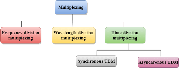
Multiplexing techniques can be classified as
Frequency-division Multiplexing (FDM)
It is an analogue technique.
A multiplexing technique used to aggregate numerous signals over a shared media is called frequency division multiplexing. Different frequency signals are combined for concurrent transmission in this kind of multiplexing. In FDM, several signals are combined and sent across a single communications line or channel, with each signal being assigned a unique frequency in the main channel.
Block Diagram
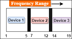
In the above diagram, a single transmission medium is subdivided into several frequency channels, and each frequency channel is given to different devices. Device 1 has a frequency channel range from 1 to 5.
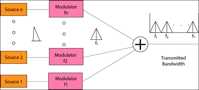
The input signals are translated into frequency bands using modulation techniques, and a multiplexer combines them to form a composite signal.
The main aim of the FDM is to subdivide the available bandwidth into different frequency channels and allocate them to different devices.
The input signals are transmitted into frequency bands using the modulation technique and then combined to form a composite signal.
The carriers that are used to modulate the signals are known as subcarriers. They are represented as f1,f2..fn.
FDM is mainly used in radio broadcasts and TV networks.
What is the Process of Frequency Division Multiplexing?
The transmitter end of the FDM system has several transmitters, while the receiver end has multiple receivers within the communication channel between the transmitter and receiver. Every transmitter in FDM transmits a signal at a distinct frequency at the transmitter end. For example, a signal with a frequency of 30 kHz is transmitted by the first transmitter, a signal with a frequency of 40 kHz by the second transmitter, and a signal with a frequency of 50 kHz by the third transmitter.
Following that, a multiplexer-a device that combines signals of different frequencies-combines the signals and broadcasts the multiplexed signals via a communication channel. FDM is a highly well-liked analogue multiplexing technique. Demultiplexers are used at the receiving end to separate the multiplexed signals before they are transmitted.
There are n channels overall in a typical FDM, where n is an integer larger than 1. Every channel has a unique carrier frequency and transmits a single bit of data. Every channel sends its output at a different frequency than the others. Each channel's input is delayed by a certain amount, dt, which can be expressed in cycles per second or time units.
The following formula can be used to determine each channel's delay:
Where T is the signal's period expressed in time units (nanoseconds in our example), constants C1, C2, and C3 are determined by the modulation technique and kind of signal being broadcast.
An assortment of photonic crystals that serve as filters for light waves travelling across them make up each channel. Only specific light wavelengths can travel through a crystal; others are entirely shut out due to the structure of the crystal or reflections from nearby crystals.
Each user using FDM needs to have a separate receiver, which can be costly and challenging to install on mobile devices. Orthogonal frequency division multiplexing (OFDM), one of the frequency modulation techniques, has been used to tackle this problem.
More receivers are needed because each mobile unit and the base station must be synchronized over time. Data cannot be sent in burst mode using this multiplexing technique; instead, data is sent continuously, requiring the receiver to wait for the next packet to be received before beginning to receive the next one. For certain receivers to effectively decode packets, they must be able to receive them at varying rates from various base stations.
The term "transmitter-receiver pair," or TRP for short, refers to the total number of transmitters and receivers used in FDM systems. The following formula can be used to get the required number of TRPs:
Advantages Of FDM:
- FDM is used for analogue signals.
- The FDM process is very simple and has easy modulation.
- A Large number of signals can be sent through an FDM simultaneously.
- It does not require any synchronization between sender and receiver.
Disadvantages Of FDM:
- The FDM technique is used only when low-speed channels are required.
- It suffers from the problem of crosstalk.
- A Large number of modulators are required.
- It requires a high bandwidth channel.
Applications Of FDM:
- FDM is commonly used in TV networks.
- It is used in FM and AM broadcasting. Each FM radio station has different frequencies, which are multiplexed to form a composite signal. The multiplexed signal is transmitted in the air.
Wavelength Division Multiplexing (WDM)
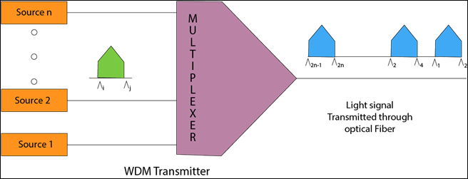
- Wavelength Division Multiplexing is the same as FDM except that the optical signals are transmitted through the fibre optic cable.
- WDM is used on fibre optics to increase the capacity of a single fibre.
- It utilizes the high data rate capability of fibre optic cable.
- It is an analogue multiplexing technique.
- Optical signals from different sources are combined to form a wider band of light with the help of a multiplexer.
- At the receiving end, the demultiplexer separates the signals to transmit them to their destinations.
- Multiplexing and Demultiplexing can be achieved by using a prism.
- Prism can perform the role of a multiplexer by combining the various optical signals to form a composite signal transmitted through an optical fibre cable.
- Prism also performs a reverse operation, i.e., demultiplexing the signal.

Advantages of Wavelength Division Multiplexing(WDM)
WDM offers the following advantages or benefits:
- It is easier to reconfigure.
- It offers a greater bandwidth.
- Given its ease of implementation, this might be the ideal strategy.
- Full duplex transmission is feasible.
- Optical parts are more dependable and comparable.
- Strong security
Disadvantages of Wavelength Division Multiplexing
The following are WDM's drawbacks:
- Signals can't be too near together.
- WDM-carrying light waves are restricted to two-point circuits.
- As optical components are added, the system's cost rises.
- WDM within PON: Ineffective use of BW, wavelength tuning challenges, and cascaded topology challenges.
- Because OLT (Optical Line Termination) requires a transmitter array with one transmitter for each ONU (Optical Network Unit), scalability is an issue. A new ONU could cause issues if the transmitters weren't pre-provisioned. Every ONU needs a laser with a particular wavelength.
Time Division Multiplexing
- It is a digital technique.
- In the Frequency Division Multiplexing Technique, all signals operate at the same time with different frequencies, but in the case of the Time Division Multiplexing technique, all signals operate at the same frequency at different times.
- In the Time Division Multiplexing technique, the total time available in the channel is distributed among different users. Therefore, each user is allocated a different time interval, known as a Time slot, at which data is to be transmitted by the sender.
- A user takes control of the channel for a fixed amount of time.
- In the Time Division Multiplexing technique, data is not transmitted simultaneously. Instead, the data is transmitted one by one.
- In TDM, the signal is transmitted in the form of frames. Frames contain a cycle of time slots in which each frame contains one or more slots dedicated to each user.
- It can be used to multiplex both digital and analogue signals but is mainly used to multiplex digital signals.
There are two types of TDM:
- Synchronous TDM
- Asynchronous TDM
Synchronous TDM
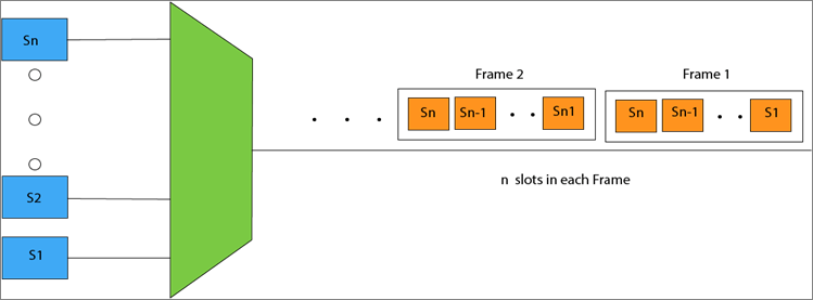
- A Synchronous TDM is a technique in which a time slot is preassigned to every device.
- In Synchronous TDM, each device is given some time slot irrespective of whether the device contains the data or not.
- If the device has no data, the slot will remain empty.
- In Synchronous TDM, signals are sent in the form of frames. Time slots are organized in the form of frames. The empty slot will be transmitted if a device does not have data for a particular time slot.
- The most popular Synchronous TDM are T-1 multiplexing, ISDN multiplexing, and SONET multiplexing.
- If there are n devices, then there are n slots.
Concept Of Synchronous TDM
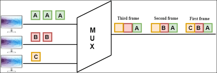
In the above figure, the Synchronous TDM technique is implemented. Each device is allocated with some time slot. The time slots are transmitted irrespective of whether the sender has data to send or not.
Disadvantages Of Synchronous TDM:
The channel's capacity is not fully utilized as the empty slots are also transmitted, which has no data. The above figure fills the first frame, but some slots are empty in the last two frames. Therefore, we can say that the channel's capacity is not utilized efficiently.
The speed of the transmission medium should be greater than the total speed of the input lines. An alternative approach to the Synchronous TDM is Asynchronous Time Division Multiplexing.
Asynchronous TDM
- An asynchronous TDM is also known as Statistical TDM.
- An asynchronous TDM is a technique in which time slots are not fixed, as in the case of Synchronous TDM. Time slots are allocated to only devices with the data to send. Therefore, we can say that the Asynchronous Time Division multiplexor transmits only the data from active workstations.
- An asynchronous TDM technique dynamically allocates the time slots to the devices.
- In Asynchronous TDM, the total speed of the input lines can be greater than the channel's capacity.
- Asynchronous time Division multiplexor accepts the incoming data streams and creates a frame that contains only data with no empty slots.
- In Asynchronous TDM, each slot contains an address part that identifies the source of the data.

- The difference between Asynchronous TDM and Synchronous TDM is that many slots in Synchronous TDM are unutilized, but in Asynchronous TDM, slots are fully utilized. This leads to a smaller transmission time and efficient channel capacity utilization.
- In Synchronous TDM, if there are n sending devices, there are n time slots. In Asynchronous TDM, if there are n sending devices, then there are m time slots where m is less than n (m<n).
- The number of slots in a frame depends on the statistical analysis of the number of input lines.
Concept Of Asynchronous TDM
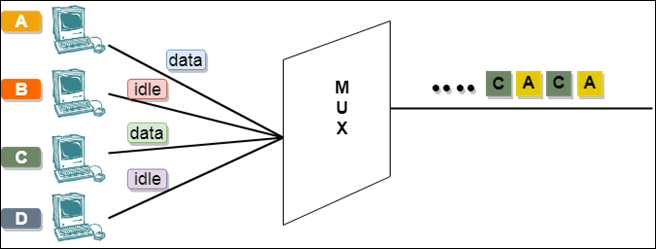
In the above diagram, there are 4 devices, but only two are sending the data, i.e., A and C. Therefore, the data of A and C are only transmitted through the transmission line.
The frame of the above diagram can be represented as:
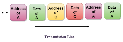
The above figure shows that the data part contains the address to determine the data source.
Difference: Synchronous TDM and Asynchronous TDM
| Synchronous TDM |
Asynchronous TDM |
| In this case, the multiplexer assigns the same time slots to every device regardless of whether or not it contains data. |
In this case, the multiplexer does not assign identical time slots to every device without considering whether or not the device has data. |
| If there are n input lines, there must be n slots in a single frame. In other words, the number of slots per frame equals the number of input lines. |
There are m slots in a single frame (m<n) if there are n input lines, which is less than the number of input lines. |
| The usage of the entire capacity link is not guaranteed. |
The usage of the entire link capacity is guaranteed. |
| The total speed of the input lines cannot exceed the path's capacity. |
The total speed of the input lines may exceed the path's capacity. |
| The number of input lines determines the time slots in a frame. |
As always, the time slots in a frame are determined by statistically analyzing how many input lines are most likely transmitting at any particular moment. |
|


 For Videos Join Our Youtube Channel: Join Now


