| |

Drafting SettingsThe categories under drafting settings are very crucial and helpful while creating drawings on the viewport in AutoCAD. It includes various settings that are present on the status bar (bottom of the screen). Status BarThe status bar looks like the below image: 
We need to write STATUSBAR on the command line and press '1' to display the status bar and press '0' to hide the status bar. We can also type '+DSETTINGS' on the command line or command prompt to open the Drafting Settings dialog box. The various settings are:
Right-click on the above icon > and click on Snap Settings. A dialog box will appear, as shown below: 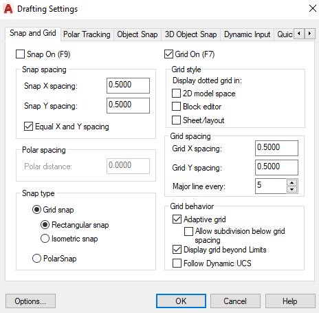
We can modify the parameters according to the requirements.
It displays the alignment paths as we move the cursor near the defined angles. We can use polar tracking with the specified polar angles of 90, 45, 30, 22.5, 18, 15, 10, and 5. We can also define an additional angle. 90 degrees is considered as the default angle. Right click on the above icon > click on Tracking Settings. A dialog box will appear, as shown below: 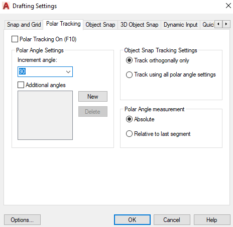
Right click on the above icon > click on Object Snap Settings. A dialog box will appear, as shown below: 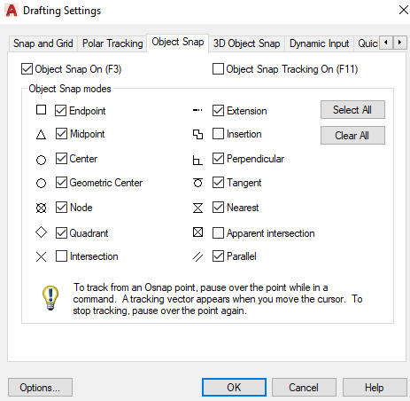
We can select the desired points according to the requirements.
The 3D Object Snap is used to specify a precise location on the 3D objects. Right-click on the above icon > click on Object Snap Settings> Click on 3D Object Snap. A dialog box will appear, as shown below: 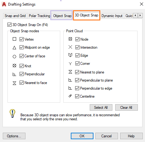
We can select the desired points according to the requirements.
The Dynamic Input in AutoCAD includes a command interface, which is provided near the cursor. The command interface is placed near the cursor on the viewport of the drawing area. Right-click on the above icon > click on Dynamic Input Settings. A dialog box will appear, as shown below: 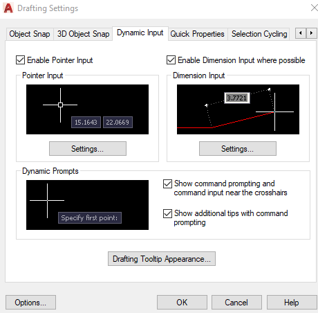
It controls the display behavior of the objects, such as overlapping objects.
Next TopicObject Snap
|


 For Videos Join Our Youtube Channel: Join Now
Feedback
- Send your Feedback to [email protected]
Help Others, Please Share


