| |

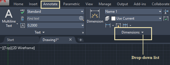
Other AutoCAD Dimension CommandsThe dimension panel consists of other common commands widely used in our drawing. To access such commands, follow the below steps:
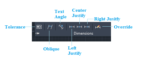
Let's discuss each command in detail.
The tolerance command is used to create geometric tolerance with the dimensions. We can also enclose geometric tolerance in a feature control frame, which can be created with a leader such as MLEADER, LEADER, and TOLERANCE. Consider the below image: 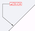
Let's understand the process of creating geometric tolerance. The steps are listed below: 1. Click on the Tolerance Or Type TOLERANCE on the command line or command prompt and press Enter. A dialog box will appear, which will look like the below image: 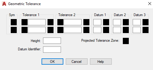
2. Specify the values of tolerance. 3. Specify the height. 4. Click on the OK button at the bottom. 5. Specify the Tolerance location on the viewport. Thus, dimension tolerance will be created.
The Oblique command is used to arrange the extension of linear dimensions in an oblique way. It is often used when an extension line of a particular dimension conflicts with other dimensions. The Oblique angle is calculated from the X-axis of the UCS. Consider the below image: 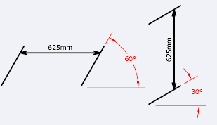
Let's understand with an example. Consider the below dimension: The steps are listed below: 1. Click on the Oblique Or Type DIMEDIT on the command line< type O< press Enter. 2. Select the object. We can also select multiple dimensions. 
3. Press Enter. 4. Enter the Oblique Here, we have specified an angle of 30. 5. Press Enter. The Oblique dimension will be created, as shown below: 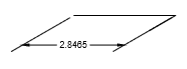
We can also verify the specified angle, as shown below: 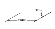
The Text Angle command is used to rotate the text in the dimension by the specified angle, as shown below: 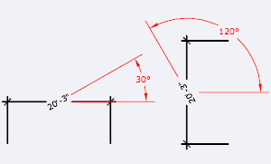
Let's understand with an example. Consider the below dimension: 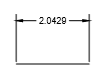
The steps to apply such dimensions are listed below:
The Text Angle dimension will be created, as shown below: 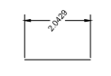
It justifies or shifts the dimensions to the left. It works only for linear, radius, and diameter dimensions. Let's understand with an example. Consider the below dimension: 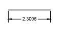
The steps are listed below:
The dimension will shift to the left. It is shown in the below image: 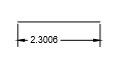
It justifies or shifts the dimensions to the center. It works only for linear, radius, and diameter dimensions. Let's understand with an example. Consider the below dimension: 
The steps are listed below:
The dimension will shift to the center. It is shown in the below image: 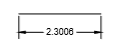
It justifies or shifts the dimensions to the right. It works only for linear, radius, and diameter dimensions. Let's understand with an example. Consider the below dimension: 
The steps are listed below:
The dimension will shift to the right. It is shown in the below image: 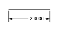
The Override command is used to control the override or clear the override of the system variables and the selected dimensions. The shortcut command is DIMOVERRIDE.
Next TopicContinue & Baseline Dimension
|
 For Videos Join Our Youtube Channel: Join Now
Feedback
- Send your Feedback to [email protected]
Help Others, Please Share


