| |

AutoCAD LoftThe loft command in AutoCAD is used to create 3D solid or surface. The 3D solid or surface is formed within the space between various cross sections. The cross-sections determine the outer shape of the solid or surface. To create a 3D object using LOFT, we are required to specify at least two cross-sections. The cross-sections and objects of Loft command can be:
Consider the below image: 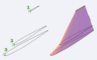
Let's understand with two examples. Example 1: Consider the below image: 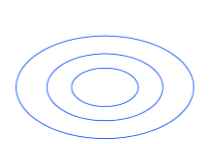
The above drawing is created in SE Isometric. We can also change the View control accordingly. The steps are listed below: 1. Create the three circles, as shown above. 2. Move the circles separately in the direction of Z-axis using the MOVE command, as shown below: 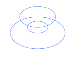
Another view is: 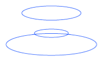
3. Select the LOFT icon from the ribbon panel, as shown below: 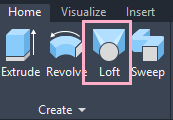
Or Type Loft on the command line < press Enter. 4. Select the cross-section (circles) to apply loft, as shown below: 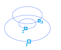
The order is shown above. 5. Press Enter. The loft will be created, as shown below: 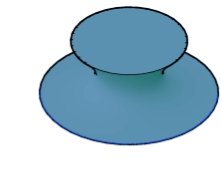
Another view is: 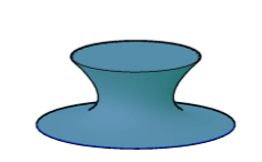
Let's change the order of the lofting, as shown below: 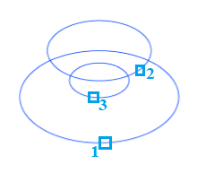
The object will now look like: 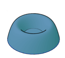
Another view is: 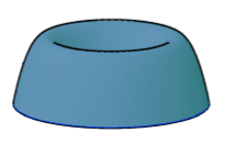
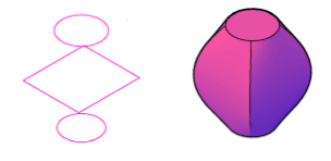
Example 2: Here, we are showing some figures before and after the loft. 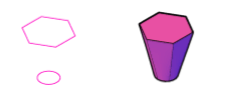
Next TopicAutoCAD Sweep
|
 For Videos Join Our Youtube Channel: Join Now
Feedback
- Send your Feedback to [email protected]
Help Others, Please Share


