| |

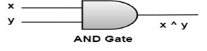
Logic Gates and Circuits:Schematic or Graphical Representation of Boolean Expressions:The Boolean expressions can be graphically represented by using logic circuits. These logic circuits can be constructed using solid-state devices called gates, which are capable of switching voltage levels. If x and y are variables, then the basic expressions x ∧ y (AND), x ∨ y (OR) and x' (NOT) are shown graphically as follows: AND Gate: An AND gate receives inputs x and y and produces output denoted x ∧ y, as shown in logic table
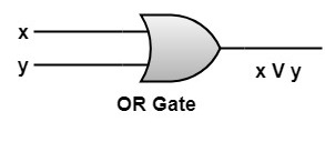
 OR Gate: An OR gate receives inputs x and y and produces output denoted x V y as shown in the logic table
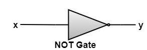
 NOT Gate: A NOT Gate receives input x and produces output y denoted x' as shown in the logic table
 We can interconnect these devices to form an electronic circuit that realizes any given Boolean Expression. Applications of Boolean Algebra in Switching Theory:The simplest switching device is NO-OFF switch. A switch is a device is an electric circuit which lets or does not let the current to flow through the circuit. The switch has two states NO or OFF (closed or open)
OFF is indicated by 0. The electrical circuits containing switches by Boolean expressions, if ON is denoted by true or 1 and OFF is denoted by False or 0. Series and Parallel Connection:There are 2 ways in which switches are connected with each other. 1. Series Connection 2. Parallel Connection 1. Series Connection: Two switches x1 and x2are said to be connected in series if current can pass only when both the switches are ON (closed),and the current does not flow if both the switches or any one are OFF (open). Symbolically, series connection of two switches x1 and x2 is denoted by x1∧ x2or x1* x2. It is represented diagrammatically as follows:  2. Parallel Connection: Two switches x1 and x2are said to be connected in parallel if current flows when both any one of the switches are ON (closed) and the current does not flow when both are OFF (open). Symbolically, Parallel connection of two switches x1 and x2 is denoted by x1∨ x2or x1+ x2. It is represented diagrammatically as follows: 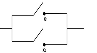
Next TopicKarnaugh Maps
|
 For Videos Join Our Youtube Channel: Join Now
Feedback
- Send your Feedback to [email protected]
Help Others, Please Share


