| |

Inductance DefinitionA conductor's capacity to hold energy in a magnetic field is called inductance, which is an electrical attribute. A magnetic field forms around a conductor as current flows through it. Electromagnetic induction is the process where a magnetic field induces a voltage in a conductor when the current changes. The strength of this effect is measured by inductance, which is expressed in Henries (H). 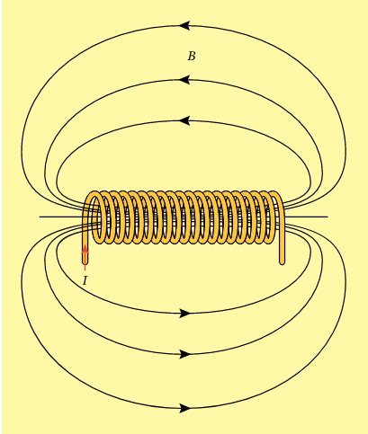
Many different electrical circuits, such as filters, oscillators, and power supplies, require inductors. Depending on the filter's design, inductors are employed to pass or block specific frequencies. Inductors are employed in oscillators to build resonant circuits that generate steady frequencies. At the peaks and troughs of the voltage waveform, inductors in power supplies store energy and release it to smooth out the output voltage. The inductance of a coil can be calculated using the formula L = N^2 * µ * A / l, where L is the inductance in the cross-sectional area of the core, and l is the length of the core. The permeability of the core material is a measure of how well it conducts magnetic fields, and it varies depending on the material. Air has a permeability of approximately 1, while iron has a permeability of approximately 1000. ExamplesThe most common example of inductance is a coil of wire, also known as an inductor. However, there are many other examples of inductance in electronics, including transformers, motors, generators, and transmission lines.
An inductor, often known as a coil of wire, is the most typical example of inductance. The conductor that makes up a coil of wire is twisted around a cylindrical core. The coil creates a magnetic field when an electrical current runs through the wire. Energy may be stored in the magnetic field, and the quantity that can be is inversely correlated with the square of the current and the number of turns in the coil. The coil's inductance, measured in henries, serves as the proportionality constant (H).
Another example of inductance is a transformer. Two coils of wire encircling a single magnetic core make up a transformer. When an electrical current passes through one coil, it generates a magnetic field that causes the other coil to produce a voltage. According to the ratio of the turns in the two coils, a certain amount of voltage is induced in the second coil. Transformers are frequently used to increase or decrease the voltage of an AC signal.
Some example of inductance are motors and generators. A coil of wire (rotor) in a motor rotates within a magnetic field produced by another coil of wire (stator). When an electrical current passes through the rotor coil, a magnetic field is produced that interacts with the magnetic field of the stator coil to cause the rotor to rotate. In contrast, a generator produces a voltage in the stator coil by rotating the rotor, which generates a shifting magnetic field.
Inductance can also be seen in transmission lines. A high-frequency electrical signal is transported along a transmission line, which is a conductor. A magnetic field is generated around a transmission line whenever an electrical signal travels through it. If the wire is not correctly terminated, this magnetic field's energy storage capacity could cause the signal to be bounced or reduced.
PCBs, or printed circuit boards, also have inductance. A layer of copper lines that connect different electrical components together makes up a printed circuit board (PCB). A magnetic field is produced around a trace when an electrical signal passes through it. This magnetic field has the potential to disrupt nearby traces and introduce noise or crosstalk into the circuit. Types of InductanceThere are several types of inductance, including self-inductance, mutual inductance, and parasitic inductance.
Self-inductance is the property of a circuit that opposes any change in the current flowing through it. It is caused by the magnetic field produced by the current flowing through the circuit. The self-inductance of a circuit is measured in henries (H) and depends on the geometry of the circuit and the material used in its construction. Self-inductance can be calculated using the following formula: L = Φ / I Where L is the self-inductance in Henries, Φ is the magnetic flux in Webers, and I is the current in amperes.
Mutual inductance is the property of a circuit that arises when the magnetic field created by one circuit induces an electromotive force (EMF) in another circuit. Mutual inductance is measured in henries (H) and depends on the geometry of the circuits and the distance between them. Mutual inductance can be calculated using the following formula: M = Φ? / I? Where M is the mutual inductance in henries, Φ? is the magnetic flux in webers created by one circuit, and I? is the current in amperes flowing through the other circuit.
Parasitic inductance is an unintended inductance that arises due to the construction of a circuit. Parasitic inductance can cause problems in high-frequency circuits, as it can reduce the speed of the circuit and increase the impedance. Parasitic inductance can be minimized by careful circuit design and the use of specialized components. For example, surface-mount technology (SMT) components are often used in high-frequency circuits, as they have a lower parasitic inductance than through-hole components.
Eddy-current inductance is a type of inductance that arises due to the presence of eddy currents in a conductor. Eddy currents are currents that are induced in a conductor when it is placed in a changing magnetic field. Eddy-current inductance can be minimized by using conductors with a low electrical conductivity, such as copper-clad steel.
EMI inductance is a type of inductance that arises due to electromagnetic interference (EMI) in a circuit. EMI can cause unwanted noise and disturbances in a circuit, which can affect the performance of the circuit. EMI inductance can be minimized by using shielded cables, filters, and other EMI-suppression techniques.
Skin effect inductance is a type of inductance that arises due to the skin effect in a conductor. The skin effect is the tendency of high-frequency currents to flow near the surface of a conductor, rather than through its interior. Skin effect inductance can be minimized by using conductors with a larger diameter, which reduce the skin effect and the inductance of the conductor. Factors Affecting InductanceInductance is an essential property of electrical circuits that plays a vital role in determining their behavior. It is a measure of the ability of an electrical component to store energy in a magnetic field, and it is dependent on several factors. These factors include the physical properties of the component, such as its shape and size, as well as the materials used in its construction. The various factors that affect inductance and how they influence the behavior of electrical circuits are discussed below: 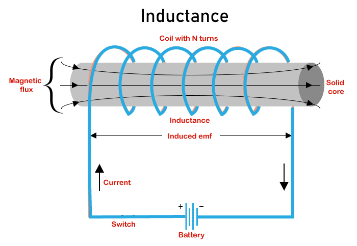
Next TopicInnovation Definition
|
 For Videos Join Our Youtube Channel: Join Now
Feedback
- Send your Feedback to [email protected]
Help Others, Please Share


